PCF8591 Programming - Part 6 (Program Development Strategy)
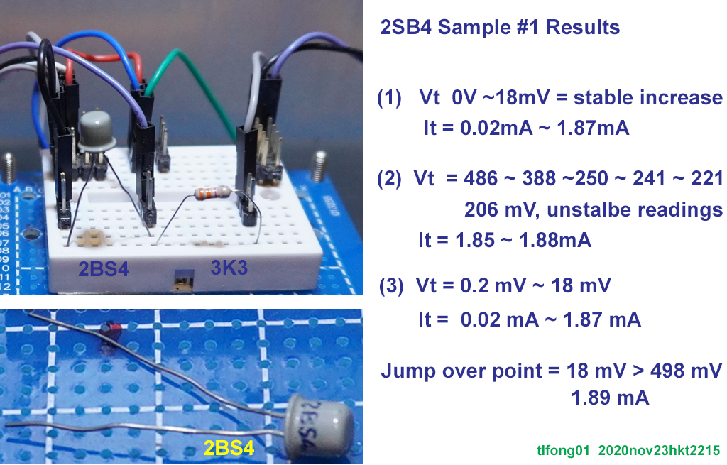
Now I am thinking how to write the python program to control the I2C PCF8591 AD/DA device to repeatedly generate a sweep signal as a power source for the tunnel diode 2SB48B
The programming strategy is summarised below.
1. Use an old I2C debugged I2C application program as a template or sketelon. This template has almost all the basic debugged I2C functions to control I2C devices.
2. The first step to develop the PCF8591 program is to insert a minimal program with just a print function. This minimal program will then be expanded to include more and more functions for the PCF8591 device.
The template program only prints the system info and the following two lines.
Begin testPcf8591
End testPcf8591
The template program is TLDR. A full listing of about 1,060+ lines is given below.
================================================
# fi2c243.py tlfong01 2020nov26hkt1617
from datetime import datetime
from time import sleep
from signal import pause
import os
import sys
import smbus
#import fprint220 as fprint
#import ftime230 as ftime
# *** Contents ***
# 00. References
# 01. I2C Bus Config
# 02. Raspbian System Config Functions
# 03. I2C General Read/Write/Print Device/Register Functions
# 04. I2C Device Config
# 05. I2C Device Functions
# 06. I2C Device Test Functions
# 07. Reserved
# 08. Reserved
# 09. Reserved
# 10. I2C Init/Main Functions
# 11. Sample Outputs
# *** 0. Programming Notes and References ***
# 0.1 Set spi.mode = 3
# 0.2 Try self test (Datasheet Page 31)
# 0.3 Power sequencing (Datasheet Page 13)
# 0.3 Power supply decoupling note - (Datasheet Page 28)
# 0.4 ADXL355 Ouput Stuck At Zero - ADI Engineering Zone 2017dec05
# I2c Bus Setup Notes
# pi@raspberrypi:~ $ date Wed 28 Aug 2019 03:26:24 PM HKT
# pi@raspberrypi:~ $ uname -a
# Linux raspberrypi 4.19.58-v7l+ #1245 SMP Fri Jul 12 17:31:45 BST 2019 armv7l GNU/Linux
# pi@raspberrypi:~ $ sudo nano /boot/config.txt
# dtoverlay=i2c1,pins_2_3 (board pins 3, 5)
# dtoverlay=i2c3,pins_4_5 (board pins 7, 29)
# dtoverlay=i2c4,pins_6_7 (board pins 31, 26)
# dtoverlay=i2c5,pins_12_13 (board pins 32, 33)
# dtoverlay=i2c6,pins_22_23 (board pins 15, 16)
# pi@raspberrypi:~ $ ls /dev/i2c*
# /dev/i2c-1 /dev/i2c-3 /dev/i2c-4 /dev/i2c-5 /dev/i2c-6
# *** 1. I2c Bus Config ***
i2cBus1 = smbus.SMBus(1)
#i2cBus3 = smbus.SMBus(3)
#i2cBus4 = smbus.SMBus(4)
#i2cBus6 = smbus.SMBus(6)
i2cBusDict = {'I2cBus1': i2cBus1,
#'I2cBus3': i2cBus3,
#'I2cBus4': i2cBus4,
#'I2cBus6': i2cBus6,
}
# *** To Debug ***
# i2cBus5 = smbus.SMBus(5) # <<< not working *** !!!
# i2cBus5': i2cBus5, # <<<<< Not working !!!
# i2cBus4 not working!!!
# *** System Functions ***
def pause(pauseTimeName):
sleep(i2cControlByteDict[pauseTimeName])
return
def convertTwoCompNumToDecNum(twoCompNum):
twoCompNumStr = bin(twoCompNum)
numBytes = 2
val = int(twoCompNumStr, numBytes)
b = val.to_bytes(numBytes, byteorder=sys.byteorder, signed = False)
return int.from_bytes(b, byteorder = sys.byteorder, signed = True)
i2cControlByteDict = {
'TenMilliSeconds' : 0.01,
'FourTimes' : 4,
'OneMillionTimes' : 1000000,
'TwentyMilliSeconds' : 0.02,
}
timeNowLong = str(datetime.now())
timeNowShort = str(datetime.now())[0:16]
# *** 2. System Config Functions ***
def getSystemInfo():
print('\n# *** System Info *****************************************************')
print('\n>>>>> ', 'Date', '<<<<<')
os.system('date')
print('\n>>>>> ', 'linux version', 'buster version, Rpi4B model, Rpi4B memory', '<<<<<')
os.system('cat /etc/issue.net')
os.system('uname -a')
os.system('grep Model /proc/cpuinfo')
os.system('grep MemTotal /proc/meminfo')
print('\n>>>>> ', 'i2c baudrate', '<<<<<')
os.system('grep dtparam=i2c /boot/config.txt')
print('\n>>>>> ', 'i2c dtoverlay', '<<<<<')
os.system('grep dtoverlay=i2c /boot/config.txt')
print('\n>>>>> ', 'ls /dev/i2c*', '<<<<<')
os.system('ls /dev/i2c*')
i2cdetectCommand = 'i2cdetect -y 1'
print('\n>>>>> ', i2cdetectCommand, '<<<<<')
os.system(i2cdetectCommand)
#i2cdetectCommand = 'i2cdetect -y 3'
#print('\n>>>>> ', i2cdetectCommand, '<<<<<')
#os.system(i2cdetectCommand)
#i2cdetectCommand = 'i2cdetect -y 4'
#print('\n>>>>> ', i2cdetectCommand, '<<<<<')
#os.system(i2cdetectCommand)
return
def getUartConfigInfo():
print('\n# *** UART BaudRate *****************************************************')
os.system('grep dtparam=i2c /boot/config.txt')
return
# *** 3. I2C Read Write Print Device/Register Functions ***
# *** Contents ***
# 3.1 quickWriteDevOneByte()
# 3.2 quickReadDevOneByte()
# 3.3 writeDevTwoBytes()
# 3.4 writeRegOneByte()
# 3.4 readDevOneByte
# 3.4 readDevReadByteAddrByteOneByte
# 3.4 readDevControlByteOneByte
# 3.4 readRegOneByte
# 3.4 printRegOneByte
# 3.4 writeDevThreeBytes
# *** Write/Read Device One Byte ***
# *** 3.1 ***
def quickWriteDevOneByte(i2cBus, devAddr, writeByte):
i2cBus.write_byte(devAddr, writeByte)
return
# *** 3.3 ***
def quickReadDevOneByte(i2cBus, devAddr):
readByte = i2cBus.read_byte(devAddr)
return readByte
# *** Write/Read/Print Device Two Bytes / Device Register One Byte ***
# *** 3.3 ***
def writeDevTwoBytes(i2cBus, devAddr, writeByte1, writeByte2):
i2cBus.write_byte_data(devAddr, writeByte1, writeByte2)
return
# *** 3.4 ***
def writeRegOneByte(i2cBus, devAddrDict, devAddrName, regAddrDict, regName, writeByte):
devAddr = devAddrDict[devAddrName]
regAddr = regAddrDict[regName]
writeDevTwoBytes(i2cBus, devAddr, regAddr, writeByte)
return
def readDevOneByte(i2cBus, devAddrAddr, readByteAddr):
readByte = i2cBus.read_byte_data(devAddr, readByteAddr)
return readByte
def readDevReadByteAddrByteOneByte(i2cBus, devAddrAddr, readByteAddr): # !!! Not Tested !!!
readByte = readDevOneByte(i2cBus, devAddrAddr, readByteAddr)
return readByte
def readDevControlByteOneByte(i2cBus, devAddr, controlByte):
readByte = i2cBus.read_byte_data(devAddr, controlByte)
return readByte
def readRegOneByte(i2cBus, devAddrDict, devName, regAddrDict, regName):
devAddr = devAddrDict[devName]
regAddr = regAddrDict[regName]
readByte = i2cBus.read_byte_data(devAddr, regAddr)
return readByte
def printRegOneByte(i2cBus, devAddrDict, devName, regAddrDict, regName):
readByte = readRegOneByte(i2cBusName, devAddrDict, devName, regAddrDict, regName)
print(printTitle, hex(readByte))
return
# *** Write Device Three Bytes ***
def writeDevThreeBytes(i2cBus, devAddr, WriteByte1, writeByte2, writByte3): # <<<<<<<<<< Not yet tested <<<<<<<<<<
i2cBus.write_block_data(devAddr, writeByte1, [writeByte2, writeByte3])
return
# *** 4. Device Write / Read / Print Register Functions ***
# *** Contents ***
# 4.1 readRegister()
# 4.2 writeVerifyRegister()
# 4.3 pingModule()
def readRegister(busName, devAddrDict, devAddrName, regAddrDict, regAddrName):
#fprint.printBeginExecFunction()
i2cBus = i2cBusDict[busName]
readByte = readRegOneByte(i2cBus, devAddrDict, devAddrName, regAddrDict, regAddrName)
#fprint.printEndExecFunction()
return readByte
def readVerifyRegister(moduleType, moduleNickName, busName, devAddrDict, devAddrName, regAddrDict, regAddrName, controlByteDict, verifyByteName):
#fprint.printBeginExecFunction()
i2cBus = i2cBusDict[busName]
verifyByte = controlByteDict[verifyByteName]
readByte = readRegOneByte(i2cBus, devAddrDict, devAddrName, regAddrDict, regAddrName)
if readByte == verifyByte:
verifyResultsString = 'Success'
else:
verifyResultsString = 'Failure'
devAddr = devAddrDict[devAddrName]
fprint.printTitleString('Date Time', fprint.indentFormat640, str(datetime.now())[0:16])
fprint.printTitleString('ModuleType', fprint.indentFormat640, moduleType)
fprint.printTitleString('ModuleNickName', fprint.indentFormat640, moduleNickName)
fprint.printTitleString('I2C Bus Name', fprint.indentFormat640, busName)
fprint.printTitleString('Device Addr Name', fprint.indentFormat640, devAddrName)
fprint.printTitleOneByteNum('Device Address', fprint.indentFormat640, devAddr)
fprint.printTitleString('Register Name', fprint.indentFormat640, regAddrName)
fprint.printTitleOneByteNum('VerifyByte', fprint.indentFormat640, verifyByte)
fprint.printTitleOneByteNum('Byte Read from Register', fprint.indentFormat640, readByte)
fprint.printTitleString('Verify Results', fprint.indentFormat640, verifyResultsString)
#fprint.printEndExecFunction()
return verifyResultsString
def writeVerifyRegister(moduleType, moduleNickName, busName, devAddrDict, devAddrName, regAddrDict, regAddrName, controlByteDict, writeByteName):
#fprint.printBeginExecFunction()
i2cBus = i2cBusDict[busName]
writeByte = controlByteDict[writeByteName]
writeRegOneByte(i2cBus, devAddrDict, devAddrName, regAddrDict, regAddrName, writeByte)
readByte = readRegOneByte(i2cBus, devAddrDict, devAddrName, regAddrDict, regAddrName)
if readByte == writeByte:
resultsString = 'Success'
else:
resultsString = 'Failure'
devAddr = devAddrDict[devAddrName]
fprint.printTitleString('Date Time', fprint.indentFormat640, str(datetime.now())[0:16])
fprint.printTitleString('ModuleType', fprint.indentFormat640, moduleType)
fprint.printTitleString('ModuleNickName', fprint.indentFormat640, moduleNickName)
fprint.printTitleString('I2C Bus Name', fprint.indentFormat640, busName)
fprint.printTitleString('Device Addr Name', fprint.indentFormat640, devAddrName)
fprint.printTitleOneByteNum('Device Address', fprint.indentFormat640, devAddr)
fprint.printTitleString('Register Name', fprint.indentFormat640, regAddrName)
fprint.printTitleOneByteNum('Byte Written to Register', fprint.indentFormat640, writeByte)
fprint.printTitleOneByteNum('Byte Read back from Register', fprint.indentFormat640, readByte)
fprint.printTitleString('Verify Results', fprint.indentFormat640, resultsString)
#fprint.printEndExecFunction()
return
def writeVerifyModuleRegister(moduleTypeName, moduleNickName, regAddrName, writeByteName):
#fprint.printBeginExecFunction()
moduleDict = moduleDictDict[moduleTypeName]
moduleType = moduleDict['ModuleType']
busName = moduleDict[moduleNickName]['I2cBusName']
controlByteDict = moduleDict['ControlByteDict']
devAddrDict = moduleDict['DevAddrDict']
devAddrName = moduleDict[moduleNickName]['DevAddrName']
regAddrDict = moduleDict['RegAddrDict']
regAddr = regAddrDict[regAddrName]
i2cBus = i2cBusDict[busName]
writeByte = controlByteDict[writeByteName]
writeRegOneByte(i2cBus, devAddrDict, devAddrName, regAddrDict, regAddrName, writeByte)
readByte = readRegOneByte(i2cBus, devAddrDict, devAddrName, regAddrDict, regAddrName)
if readByte == writeByte:
writeVerifyResultsString = 'Success'
else:
writeVerifyResultsString = 'Failure'
devAddr = devAddrDict[devAddrName]
fprint.printTitleString('Date Time', fprint.indentFormat640, str(datetime.now())[0:16])
fprint.printTitleString('ModuleType', fprint.indentFormat640, moduleType)
fprint.printTitleString('ModuleNickName', fprint.indentFormat640, moduleNickName)
fprint.printTitleString('I2C Bus Name', fprint.indentFormat640, busName)
fprint.printTitleString('Device Addr Name', fprint.indentFormat640, devAddrName)
fprint.printTitleOneByteNum('Device Address Byte', fprint.indentFormat640, devAddr)
fprint.printTitleString('Register Name', fprint.indentFormat640, regAddrName)
fprint.printTitleOneByteNum('Register Address Byte', fprint.indentFormat640, regAddr)
fprint.printTitleString('WriteByteName', fprint.indentFormat640, writeByteName)
fprint.printTitleOneByteNum('WriteByte (Written to Register)', fprint.indentFormat640, writeByte)
fprint.printTitleOneByteNum('ReadByte (Read from Register)', fprint.indentFormat640, readByte)
fprint.printTitleString('Write Verify Results', fprint.indentFormat640, writeVerifyResultsString)
#fprint.printEndExecFunction()
return writeVerifyResultsString
# Notes
# For Mode1 register, Test byte 0x88, 0x77 returns 0x58, 0x77. In other words, some bits are hardwired.
def pingModule(moduleTypeName, moduleNickName):
#fprint.printBeginExecFunction()
moduleDict = moduleDictDict[moduleTypeName]
moduleType = moduleDict['ModuleType']
busName = moduleDict[moduleNickName]['I2cBusName']
controlByteDict = moduleDict['ControlByteDict']
devAddrDict = moduleDict['DevAddrDict']
devAddrName = moduleDict[moduleNickName]['DevAddrName']
regAddrDict = moduleDict['RegAddrDict']
regAddrName = moduleDict['PingRegAddrName']
writeByteName = moduleDict['PingWriteByteName']
writeVerifyRegister(moduleType, moduleNickName, busName, devAddrDict, devAddrName, regAddrDict, regAddrName,
controlByteDict, writeByteName)
#fprint.printEndExecFunction()
return
def pingModuleList(moduleType, moduleNickNameList):
for moduleNickName in moduleNickNameList:
pingModule(moduleType, moduleNickName)
return
def readModuleRegister(moduleTypeName, moduleNickName, regAddrName):
#fprint.printBeginExecFunction()
moduleDict = moduleDictDict[moduleTypeName]
moduleType = moduleDict['ModuleType']
busName = moduleDict[moduleNickName]['I2cBusName']
controlByteDict = moduleDict['ControlByteDict']
devAddrDict = moduleDict['DevAddrDict']
devAddrName = moduleDict[moduleNickName]['DevAddrName']
regAddrDict = moduleDict['RegAddrDict']
readByte = readRegister(busName, devAddrDict, devAddrName, regAddrDict, regAddrName)
#fprint.printEndExecFunction()
return readByte
def readRegister(busName, devAddrDict, devAddrName, regAddrDict, regAddrName):
#fprint.printBeginExecFunction()
i2cBus = i2cBusDict[busName]
readByte = readRegOneByte(i2cBus, devAddrDict, devAddrName, regAddrDict, regAddrName)
#fprint.printEndExecFunction()
return readByte
def readVerifyModuleRegister(moduleTypeName, moduleNickName, registerName, verifyByteName):
#fprint.printBeginExecFunction()
moduleDict = moduleDictDict[moduleTypeName]
moduleType = moduleDict['ModuleType']
busName = moduleDict[moduleNickName]['I2cBusName']
controlByteDict = moduleDict['ControlByteDict']
devAddrDict = moduleDict['DevAddrDict']
devAddrName = moduleDict[moduleNickName]['DevAddrName']
regAddrDict = moduleDict['RegAddrDict']
regAddrName = moduleDict['PingRegAddrName']
readVerifyResult = readVerifyRegister(moduleType, moduleNickName, busName, devAddrDict, devAddrName,
regAddrDict, regAddrName, controlByteDict, verifyByteName)
#fprint.printEndExecFunction()
return
# *** 5. Device Config ***
# Contents
# 5.1 PCF8591 ADC/DAC Config
# 5.2 PCA9685 PWM Controller Config
# 5.3. MCP23017 IOX Config
# 5.4 ADXL345 Accelero Sensor Config
# *** 5.1 PCF8591 ADC/DAC Config ***
pcf8591DevAddrDict = {
'DevAddr0': 0x48,
'DevAddr1': 0x49,
'DevAddr2': 0x4a,
'DevAddr3': 0x4b,
'DevAddr4': 0x4c,
'DevAddr5': 0x4d,
'DevAddr6': 0x4e,
'DevAddr7': 0x4f,
}
pcf8591ControlByteDict = {
'ChannelNum0': 0x00,
'ChannelNum1': 0x01,
}
pcf8591ModuleDict = {
'ModuleType' : 'PCA9685',
#'ModuleHelp' : 'PwmControllerHelp',
#'DevAddrDict' : pca9685DevAddrDict,
#'RegAddrDict' : pca9685RegAddrDict,
#'ControlByteDict': pca9685ControlByteDict,
#'PingRegAddrName': 'Mode1',
'GreenTea': {'SignalName' : 'GreenTea',
'I2cBusName' : 'I2cBus4',
'DevAddrName' : 'DevAddr0',
'ChannelNumName' : 'ChannelNum0',
},
'Milk' : {'SignalName' : 'Yvalue',
'I2cBusName' : 'I2cBus4',
'DevAddrName' : 'DevAddr1',
'ChannelNumName': 'ChannelNum0',
},
'Water' : {'SignalName' : 'Yvalue',
'I2cBusName' : 'I2cBus4',
'DevAddrName' : 'DevAddr0',
'ChannelNumName': 'ChannelNum0',
},
'Oil' : {'SignalName' : 'Yvalue',
'I2cBusName' : 'I2cBus4',
'DevAddrName' : 'DevAddr1',
'ChannelNumName': 'ChannelNum0',
},
}
# *** 5.2 PCA9685 PWM Controller Config ***
pca9685DevAddrDict = {
'DevAddr0': 0x40,
'DevAddr1': 0x41,
'DevAddr2': 0x40,
'DevAddr3': 0x43,
'DevAddr4': 0x44,
'DevAddr5': 0x45,
'DevAddr6': 0x46,
'DevAddr7': 0x47,
}
pca9685RegAddrDict = { 'Mode1': 0x00,
'Mode2': 0x01,
}
pca9685ControlByteDict = {
'DataByte0x75' : 0x75,
'PingWriteByte' : 0x75,
}
pca9685ModuleDict = {
'ModuleType' : 'PCA9685',
'ModuleHelp' : 'PwmControllerHelp',
'DevAddrDict' : pca9685DevAddrDict,
'RegAddrDict' : pca9685RegAddrDict,
'ControlByteDict' : pca9685ControlByteDict,
'PingRegAddrName' : 'Mode1',
'PingWriteByteName' : 'PingWriteByte',
'Amy' : {'I2cBusName' : 'I2cBus1',
'DevAddrName' : 'DevAddr0',
},
'Betty' : {'I2cBusName' : 'I2cBus1',
'DevAddrName' : 'DevAddr1',
},
'Cindy' : {'I2cBusName' : 'I2cBus3',
'DevAddrName' : 'DevAddr0',
},
'Daisy' : {'I2cBusName' : 'I2cBus3',
'DevAddrName' : 'DevAddr2',
},
}
# *** 5.3 MCP23017 Iox Config ***
mcp23017DevAddrDict = {
'DevAddr0': 0x20,
'DevAddr1': 0x21,
'DevAddr2': 0x20,
'DevAddr3': 0x23,
'DevAddr4': 0x24,
'DevAddr5': 0x25,
'DevAddr6': 0x26,
'DevAddr7': 0x27,
}
mcp23017RegAddrDict = { 'IoDirRegAddrByteA': 0x00, }
mcp23017ControlByteDict = {
'DataByte0x55' : 0x55,
'DataByte0xaa' : 0xaa,
'PingWriteByte' : 0x55,
}
mcp23017ModuleDict = {
'ModuleType' : 'MCP23017',
'ModuleHelp' : 'Mcp23017IoxHelp',
'DevAddrDict' : mcp23017DevAddrDict,
'RegAddrDict' : mcp23017RegAddrDict,
'ControlByteDict' : mcp23017ControlByteDict,
'PingRegAddrName' : 'IoDirRegAddrByteA',
'PingWriteByteName' : 'PingWriteByte',
'Emily' : {'I2cBusName' : 'I2cBus1',
'DevAddrName' : 'DevAddr0',
},
'Fanny' : {'I2cBusName' : 'I2cBus1',
'DevAddrName' : 'DevAddr1',
},
'Gracie' : {'I2cBusName' : 'I2cBus1',
'DevAddrName' : 'DevAddr2',
},
'Heidi' : {'I2cBusName' : 'I2cBus1',
'DevAddrName' : 'DevAddr3',
},
'Ivy' : {'I2cBusName' : 'I2cBus1',
'DevAddrName' : 'DevAddr4',
},
}
# *** 5.4 ADXL345 Accelero Sensor Config ***
adxl345DevAddrDict = {
'DevAddr0': 0x1d,
}
adxl345RegAddrDict = {
'DevIdReg' : 0x00,
'DataFormatReg' : 0x31,
'PowerControlReg' : 0x2d,
'InterruptConfigReg' : 0x2e,
'DataX0' : 0x32,
'DataX1' : 0x33,
'DataY0' : 0x34,
'DataY1' : 0x35,
'DataZ0' : 0x36,
'DataZ1' : 0x37,
}
adxl345ControlByteDict = {
'DevIdByte' : 0xe5,
'Format16G13Bit' : 0x0B,
'StartMeasurement' : 0x08,
'InterruptDataReadyEnable' : 0x80,
'InterruptDataRedayDisable' : 0x00,
}
adxl345ModuleDict = {
'ModuleType' : 'ADXL345',
'ModuleHelp' : 'Adxl345AccelerometerHelp',
'DevAddrDict' : adxl345DevAddrDict,
'RegAddrDict' : adxl345RegAddrDict,
'ControlByteDict' : adxl345ControlByteDict,
'PingRegAddrName' : 'DevIdReg',
'PingWriteByteName' : 'DevIdByte',
'Jenny' : {'I2cBusName' : 'I2cBus1',
'DevAddrName' : 'DevAddr0',
},
}
# *** Module Dict Dict ***
moduleDictDict = {
'Pcf8591' : pcf8591ModuleDict,
'Pca9685' : pca9685ModuleDict,
'Mcp23017' : mcp23017ModuleDict,
'Adxl345' : adxl345ModuleDict,
}
# *** 6. Device Functions
# *** 6.1 PCF8591 ADC/DAC PhMeter ADC And Test Functions ***
# *** Read PCF8591 Single Ended Input Channel 0 ***
#def readAdcResults(i2cBus, devAddr, controlByte):
# adcResults = i2cBus.read_byte_data(devAddr, controlByte)
# adcResults = i2cBus.read_byte_data(devAddr, controlByte)
# return adcResults
# *** Device Functions ***
def pcf8591ConvertModule(moduleNickName):
# fprint.printBeginExecFunction()
moduleType = pcf8591ModuleDict['ModuleType']
i2cBusName = pcf8591ModuleDict[moduleNickName]['I2cBusName']
devAddrName = pcf8591ModuleDict[moduleNickName]['DevAddrName']
channelNumName = pcf8591ModuleDict[moduleNickName]['ChannelNumName']
i2cBus = i2cBusDict[i2cBusName]
devAddr = pcf8591DevAddrDict[devAddrName]
controlByte = pcf8591ControlByteDict[channelNumName]
# adcResults = readAdcResults(i2cBus, devAddr, controlByte)
adcResults = readDevControlByteOneByte(i2cBus, devAddr, controlByte)
adcResults = readDevControlByteOneByte(i2cBus, devAddr, controlByte)
print('\n# *** PCF8591 ADC Testing *****************************************************\n')
fprint.printTitleString('Module Type', fprint.indentFormat640, moduleType)
fprint.printTitleString('Module Nick Name', fprint.indentFormat640, moduleNickName)
fprint.printTitleString('I2C Bus Name', fprint.indentFormat640, i2cBusName)
fprint.printTitleOneByteNum('PCF8591 I2C Device Addr', fprint.indentFormat640, devAddr)
fprint.printTitleOneByteNum('Channel Number', fprint.indentFormat640, pcf8591ControlByteDict[channelNumName])
print(' ADC Results =', fprint.convertOneByteNumToFourCharStr(adcResults), ' (hex)')
print(' =', (str(adcResults)).ljust(4, ' '), ' (dec)')
print(' =', (str(int((float((adcResults)/255) * 100)))).ljust(4, ' '), ' (%)')
# fprint.printEndExecFunction()
return
def pcf8591ConvertModuleList(moduleNickNameList):
for moduleNickName in moduleNickNameList:
pcf8591ConvertModule(moduleNickName)
return
# *** PCF8591 ADC Test Functions ***
def testPcf8591ConvertDefaultModule():
pcf8591ConvertModule('GreenTea')
return
def testPcf8591ConvertModules():
pcf8591ConvertModule('GreenTea')
pcf8591ConvertModule('Milk')
pcf8591ConvertModule('Water')
pcf8591ConvertModule('Oil')
return
def testPcf8591ConvertModuleList():
pcf8591ConvertModuleList(['GreenTea', 'Milk', 'Water', 'Oil'])
return
# *** 6.2 PCA9865 PWM Controller Functions***
# *** Device Functions ***
# *** PCA9685 PWM Controller Functions ***
# *** Test Functions ***
# *** Test Repeat Write Register ***
# *** Test Repeat Write to PCA9685 PWM Controller ***
def testRepeatWriteRegister(): # <<<<<<<<<< Not tested!!!
getSystemConfig()
testRepeatWriteReadRegisterNoPrintResults('PCA9685', 'I2cBus1', 'Dev0', 'Mode1', '0x75', 'TenMilliSeconds', 'FourTimes')
testRepeatWriteReadRegisterNoPrintResults('PCA9685', 'I2cBus1', 'Dev0', 'Mode1', '0x75', 'TenMilliSeconds', 'OneMillionTimes')
return
# *** Test PCA9685 ***
def testPca9685PingDefaultModule():
pingModule('Pca9685', 'Amy')
return
def testPca9685PingModules():
pingModule('Pca9685', 'Amy')
pingModule('Pca9685', 'Betty')
pingModule('Pca9685', 'Cindy')
pingModule('Pca9685', 'Daisy')
return
def testPca9685PingModuleList():
pingModuleList('Pca9685', ['Amy', 'Betty', 'Cindy', 'Daisy'])
return
# *** Test MCP23017 ***
def testMcp23017PingDefaultModule():
pingModule('Mcp23017', 'Emily')
return
def testMcp23017PingModules():
pingModule('Mcp23017', 'Emily')
pingModule('Mcp23017', 'Fanny')
pingModule('Mcp23017', 'Gracie')
pingModule('Mcp23017', 'Heidi')
pingModule('Mcp23017', 'Ivy')
return
def testMcp23017PingModuleList():
pingModuleList('Mcp23017', ['Emily', 'Fanny', 'Gracie', 'Heidi', 'Ivy'])
return
# *** Test ADXL345 Accelerometer ***
def adxl345CheckDeviceId(moduleNickName):
#fprint.printBeginExecFunction()
# *** Ping Module ***
#pingModule('Adxl345', 'Jenny')
# *** Verify Mdoule Device Id ***
moduleTypeName = 'Adxl345'
print(' ----------------------------------------------------------------------')
readVerifyModuleRegister(moduleTypeName, moduleNickName, 'DevIdReg', 'DevIdByte')
#fprint.printEndExecFunction()
return
def testAdxl345PingDefaultModule():
fprint.printBeginExecFunction()
# *** Ping Module ***
#pingModule('Adxl345', 'Jenny')
# *** Verify Mdoule Device Id ***
readVerifyModuleRegister('Adxl345', 'Jenny', 'DevIdReg', 'DevIdByte')
fprint.printEndExecFunction()
return
# To delete 2019dec08hkt1456
#testWriteReadRegister('ADXL345', 'I2cBus1',
# adxl345DevAddrDict, 'DevAddr0',
# adxl345RegAddrDict, 'DeviceId',
# adxl345ControlByteDict, 'DataByte0x55')
#readByte = ReadRegister('I2cBus1', adxl345DevAddrDict, 'DevAddr0', adxl345RegAddrDict, 'DeviceId')
#print('Adxl345 DeviceId Reg =', hex(readByte))
def adxl345Init(moduleNickName):
moduleTypeName = 'Adxl345'
print(' ----------------------------------------------------------------------')
writeVerifyModuleRegister(moduleTypeName, moduleNickName, 'DataFormatReg', 'Format16G13Bit')
print(' ----------------------------------------------------------------------')
writeVerifyModuleRegister(moduleTypeName, moduleNickName, 'PowerControlReg', 'StartMeasurement')
print(' ----------------------------------------------------------------------')
writeVerifyModuleRegister(moduleTypeName, moduleNickName, 'InterruptConfigReg', 'InterruptDataReadyEnable')
print(' ----------------------------------------------------------------------')
pause('TwentyMilliSeconds')
return
def adxl345ReadOutput(moduleNickName):
moduleTypeName = 'Adxl345'
x0 = readModuleRegister(moduleTypeName, moduleNickName, 'DataX0')
x1 = readModuleRegister(moduleTypeName, moduleNickName, 'DataX0')
y0 = readModuleRegister(moduleTypeName, moduleNickName, 'DataY0')
y1 = readModuleRegister(moduleTypeName, moduleNickName, 'DataY1')
z0 = readModuleRegister(moduleTypeName, moduleNickName, 'DataZ0')
z1 = readModuleRegister(moduleTypeName, moduleNickName, 'DataZ1')
xTwoComp = (x1 << 8) | x0
yTwoComp = (y1 << 8) | y0
zTwoComp = (z1 << 8) | z0
xDecNum = convertTwoCompNumToDecNum(xTwoComp)
yDecNum = convertTwoCompNumToDecNum(yTwoComp)
zDecNum = convertTwoCompNumToDecNum(zTwoComp)
adxl345OutputList = [xDecNum, yDecNum, zDecNum]
#print(' x1, x0, y1, y0, z1, z0 =', hex(x1), hex(x0), ' ', hex(y1), hex(y0), ' ', hex(z1), hex(z0))
#print(x, ' ', y, ' ', z)
#print(hex(x), ' ', hex(y), ' ', hex(z))
#fprint.printTitleString('x, y, z', fprint.indentFormat640, (hex(x) + ' ' + hex(y) + ' ' + hex(z)))
#fprint.printTitleString('x, y, z', fprint.indentFormat640, (bin(x) + ' ' + bin(y) + ' ' + bin(z)))
#x18BitStr = fprint.convertTwoOneByteNumToEighteenBitStr(x0, x1)
#y18BitStr = fprint.convertTwoOneByteNumToEighteenBitStr(y0, y1)
#z18BitStr = fprint.convertTwoOneByteNumToEighteenBitStr(z0, z1)
#fprint.printTitleString('x', fprint.indentFormat608, x18BitStr)
#fprint.printTitleString('y', fprint.indentFormat608, y18BitStr)
#fprint.printTitleString('z', fprint.indentFormat608, z18BitStr)
return adxl345OutputList
def testAdxl345DefaultModule():
#os.system('i2cdetect -y 1')
adxl345CheckDeviceId('Jenny')
adxl345Init('Jenny')
print('')
print(' ----------------------------------------------------------------------')
fprint.printTitleString(' Time', fprint.indentFormat640, ' X value Y Value Z Value')
print(' ----------------------------------------------------------------------')
totalCount = 4
for count in range(totalCount):
adxl345OutputList = adxl345ReadOutput('Jenny')
outputListStr = str(adxl345OutputList[0]).rjust(8) + ' ' + str(adxl345OutputList[1]).rjust(8) + ' ' + str(adxl345OutputList[2]).rjust(8)
fprint.printTitleString(str(count).rjust(4) + ' ' + str(datetime.now()), fprint.indentFormat640, outputListStr)
sleep(0.5)
print(' ----------------------------------------------------------------------')
return
# *** Test All In One ***
def testAllInOne():
# *** Get System Info***
getSystemInfo()
# *** Test Pcf8591 ADC/DAC ***
#testPcf8591ConvertDefaultModule()
#testPcf8591ConvertModules()
#testPcf8591ConvertModuleList()
# *** Test Pca9685 PWM Controller ***
#testPca9685PingDefaultModule()
#testPca9685PingModules()
#testPca9685PingModuleList()
# *** Test Mcp23017 GPIO Expander ***
#testMcp23017PingDefaultModule()
#testMcp23017PingModules()
#testMcp23017PingModuleList()
# *** Test Adxl345 Accelerometer ***
testAdxl345DefaultModule()
return
# ****************************************************************************************
# ****************************************************************************************
# ****************************************************************************************
# ****************************************************************************************
# ****************************************************************************************
# ****************************************************************************************
# ****************************************************************************************
# ****************************************************************************************
# *** PCF8591 - tlfong01 2020nov26hkt1606 ***
def testPcf8591():
print('Begin testPcf8591')
print('End testPcf8591')
return
# *** 10. Init/Main Function ***
def init():
pass
return
def main():
#init()
#testAllInOne()
#testAdxl345DefaultModule()
#getSystemInfo()
#os.system('grep dtparam=i2c /boot/config.txt')
#print(' ')
#getSystemInfo()
#os.system('i2cdetect -y 1')
#adxl345CheckDeviceId('Jenny')
#adxl345Init('Jenny')
#testAdxl345DefaultModule()
getSystemInfo()
os.system('grep dtparam=i2c /boot/config.txt')
print(' ')
testPcf8591()
return
if __name__ == '__main__':
main()
# *** End of Program ********************************************************************
# *** 11. Sample Outputs ***
'''
# *** System Info *****************************************************
>>> %Run pcf8591v242.py
# *** System Info *****************************************************
>>>>> Date <<<<<
Thu 26 Nov 2020 04:16:57 PM HKT
>>>>> linux version buster version, Rpi4B model, Rpi4B memory <<<<<
Raspbian GNU/Linux 10
Linux raspberrypi 4.19.118-v7l+ #1311 SMP Mon Apr 27 14:26:42 BST 2020 armv7l GNU/Linux
Model : Raspberry Pi 4 Model B Rev 1.2
MemTotal: 3999744 kB
>>>>> i2c baudrate <<<<<
dtparam=i2c_arm=on
>>>>> i2c dtoverlay <<<<<
>>>>> ls /dev/i2c* <<<<<
/dev/i2c-1
>>>>> i2cdetect -y 1 <<<<<
0 1 2 3 4 5 6 7 8 9 a b c d e f
00: -- -- -- -- -- -- -- -- -- -- -- -- --
10: -- -- -- -- -- -- -- -- -- -- -- -- -- -- -- --
20: -- -- -- -- -- -- -- -- -- -- -- -- -- -- -- --
30: -- -- -- -- -- -- -- -- -- -- -- -- -- -- -- --
40: -- -- -- -- -- -- -- -- 48 -- -- -- -- -- -- --
50: -- -- -- -- -- -- -- -- -- -- -- -- -- -- -- --
60: -- -- -- -- -- -- -- -- -- -- -- -- -- -- -- --
70: -- -- -- -- -- -- -- --
dtparam=i2c_arm=on
Begin testPcf8591
End testPcf8591
>>>
==========
>>>>> Date <<<<<
Thu 26 Nov 2020 03:56:34 PM HKT
>>>>> linux version buster version, Rpi4B model, Rpi4B memory <<<<<
Raspbian GNU/Linux 10
Linux raspberrypi 4.19.118-v7l+ #1311 SMP Mon Apr 27 14:26:42 BST 2020 armv7l GNU/Linux
Model : Raspberry Pi 4 Model B Rev 1.2
MemTotal: 3999744 kB
>>>>> i2c baudrate <<<<<
dtparam=i2c_arm=on
>>>>> i2c dtoverlay <<<<<
>>>>> ls /dev/i2c* <<<<<
/dev/i2c-1
>>>>> i2cdetect -y 1 <<<<<
0 1 2 3 4 5 6 7 8 9 a b c d e f
00: -- -- -- -- -- -- -- -- -- -- -- -- --
10: -- -- -- -- -- -- -- -- -- -- -- -- -- -- -- --
20: -- -- -- -- -- -- -- -- -- -- -- -- -- -- -- --
30: -- -- -- -- -- -- -- -- -- -- -- -- -- -- -- --
40: -- -- -- -- -- -- -- -- 48 -- -- -- -- -- -- --
50: -- -- -- -- -- -- -- -- -- -- -- -- -- -- -- --
60: -- -- -- -- -- -- -- -- -- -- -- -- -- -- -- --
70: -- -- -- -- -- -- -- --
>>>
==========
>>> %Run fi2c227.py
# *** System Info *****************************************************
>>>>> Date <<<<<
Mon 30 Dec 2019 09:36:33 AM HKT
>>>>> linux version buster version, Rpi4B model, Rpi4B memory <<<<<
Raspbian GNU/Linux 10
Linux raspberrypi 4.19.75-v7l+ #1270 SMP Tue Sep 24 18:51:41 BST 2019 armv7l GNU/Linux
Model : Raspberry Pi 4 Model B Rev 1.1
MemTotal: 1986024 kB
>>>>> i2c baudrate <<<<<
dtparam=i2c_arm=on,i2c_arm_baudrate=50000
>>>>> i2c dtoverlay <<<<<
dtoverlay=i2c1,pins_2_3 (board pins 3, 5)
dtoverlay=i2c3,pins_4_5 (board pins 7, 29)
dtoverlay=i2c4,pins_6_7 (board pins 31, 26)
dtoverlay=i2c5,pins_12_13 (board pins 32, 33)
dtoverlay=i2c6,pins_22_23 (board pins 15, 16)
>>>>> ls /dev/i2c* <<<<<
/dev/i2c-1
/dev/i2c-3
/dev/i2c-4
/dev/i2c-5
/dev/i2c-6
>>>>> i2cdetect -y 1 <<<<<
0 1 2 3 4 5 6 7 8 9 a b c d e f
00: -- -- -- -- -- -- -- -- -- -- -- -- --
10: -- -- -- -- -- -- -- -- -- -- -- -- -- 1d -- --
20: -- -- -- -- -- -- -- -- -- -- -- -- -- -- -- --
30: -- -- -- -- -- -- -- -- -- -- -- -- 3c -- -- --
40: 40 -- 42 -- -- -- -- -- -- -- -- -- -- -- -- --
50: -- -- -- -- -- -- -- -- -- -- -- -- -- -- -- --
60: -- -- -- -- -- -- -- -- -- -- -- -- -- -- -- --
70: 70 -- -- -- -- -- -- --
----------------------------------------------------------------------
Date Time = 2019-12-30 09:36
ModuleType = ADXL345
ModuleNickName = Jenny
I2C Bus Name = I2cBus1
Device Addr Name = DevAddr0
Device Address = 0x1d
Register Name = DevIdReg
VerifyByte = 0xe5
Byte Read from Register = 0xe5
Verify Results = Success
----------------------------------------------------------------------
Date Time = 2019-12-30 09:36
ModuleType = ADXL345
ModuleNickName = Jenny
I2C Bus Name = I2cBus1
Device Addr Name = DevAddr0
Device Address Byte = 0x1d
Register Name = DataFormatReg
Register Address Byte = 0x31
WriteByteName = Format16G13Bit
WriteByte (Written to Register) = 0x0b
ReadByte (Read from Register) = 0x0b
Write Verify Results = Success
----------------------------------------------------------------------
Date Time = 2019-12-30 09:36
ModuleType = ADXL345
ModuleNickName = Jenny
I2C Bus Name = I2cBus1
Device Addr Name = DevAddr0
Device Address Byte = 0x1d
Register Name = PowerControlReg
Register Address Byte = 0x2d
WriteByteName = StartMeasurement
WriteByte (Written to Register) = 0x08
ReadByte (Read from Register) = 0x08
Write Verify Results = Success
----------------------------------------------------------------------
Date Time = 2019-12-30 09:36
ModuleType = ADXL345
ModuleNickName = Jenny
I2C Bus Name = I2cBus1
Device Addr Name = DevAddr0
Device Address Byte = 0x1d
Register Name = InterruptConfigReg
Register Address Byte = 0x2e
WriteByteName = InterruptDataReadyEnable
WriteByte (Written to Register) = 0x80
ReadByte (Read from Register) = 0x80
Write Verify Results = Success
----------------------------------------------------------------------
----------------------------------------------------------------------
Time = X value Y Value Z Value
----------------------------------------------------------------------
0 2019-12-30 09:36:34.136020 = -17220 -134 1511
1 2019-12-30 09:36:34.650973 = -16706 -134 1510
2 2019-12-30 09:36:35.165727 = -16963 -133 1512
3 2019-12-30 09:36:35.680478 = -16449 -135 1512
----------------------------------------------------------------------
>>>
'''
# *** End of Sample Output ***